
________________________________________
This command lets you quickly and easily create gears, racks and sprockets.

The Gear, Rack, or Sprocket command is available by right-clicking on the Shapes button. You can also press the G key.
The new gear is drawn on the grid that shows the cutting table. The size of the gear depends on the number of teeth and the pitch you selected. The pitch circle is drawn with the gear, and provides a convenient measuring point for the center of the gear.
Depending on whether you have chosen English or metric units, there are some differences in creating the gear.
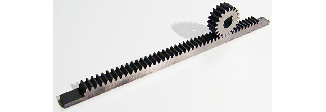
A gear and rack made by the GlobalMAX
Not all possible combinations of Pitch, Pressure Angle, and Number of teeth are supported or recommended. Use of gears with high pressure angles (for example, greater than 25 degrees) is generally not recommended. From a design point of view, high pressure angles result in high bearing loads on the gears, and from the Gear Generator’s point of view, they also do not calculate well and are limited in the number of teeth supported to make the gear. Hand-editing the gears after the calculation has been made may be required to get good results with high pressure angles and many teeth.
When the Units are set to any English measurement (inches or feet), then the gear is created in inches, using the English gear dialog. English gears with the same pitch and pressure angle will always mesh together properly, regardless of the number of teeth.
1. Right-click on Shapes on the left side of the screen.
2. Choose Gear, Rack or Sprocket from the drop-down menu.
3. The Gear, Rack, and Sprocket Shapes Generator dialog is displayed. Use this dialog to select your Shape Type: English external (spur) gear, English internal gear, English Rack, or Sprocket.
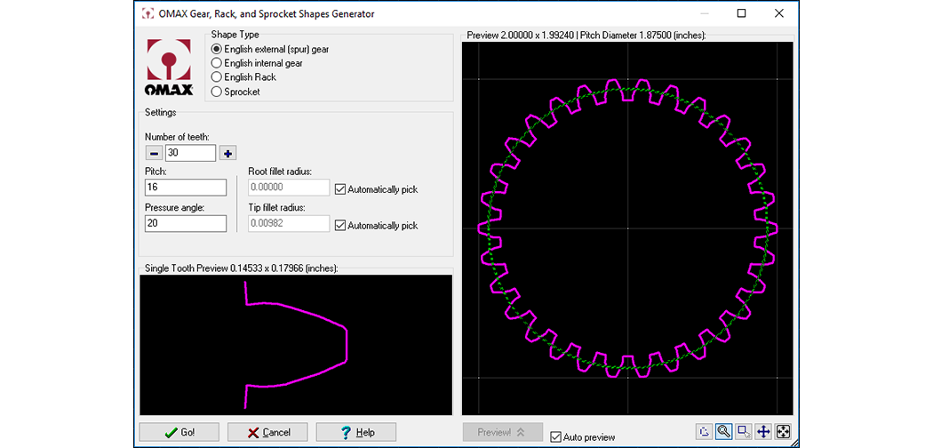
The large preview window on the right shows the gear that will be generated as a result of the current values. Another window shows a view of a single tooth. Zoom in and out in both of these windows by moving the cursor over the window and using the left mouse button to zoom in and the right mouse button to zoom out.
Choose what you want to create. An external gear is a gear designed to mesh on the outside of the circle. An internal gear is designed to mesh inside the circle, and a rack is straight.
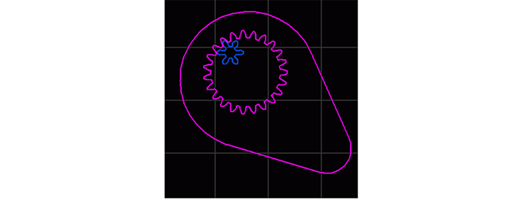
The blue gear is an external gear, the purple gear is an internal gear
Enter the number of teeth in the gear. The + and - buttons may also be used to increase and decrease the number of teeth.
Enter the diametral pitch of the gear. The diametral pitch (P) is a ratio of the number of teeth (N) to the pitch circle diameter (d), P=N/d. The smaller the diametral pitch, the larger the pitch circle diameter, creating a larger gear.
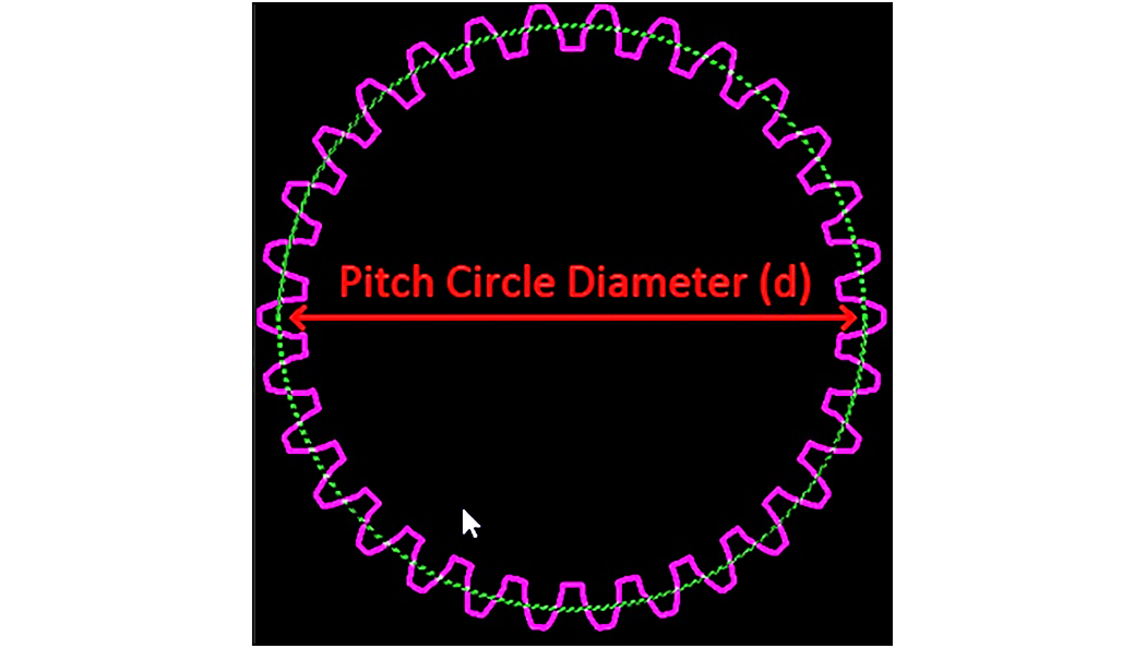
Pitch Circle (green), Pitch Circle Diameter (red)
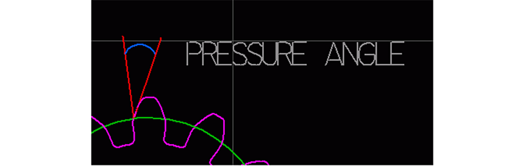
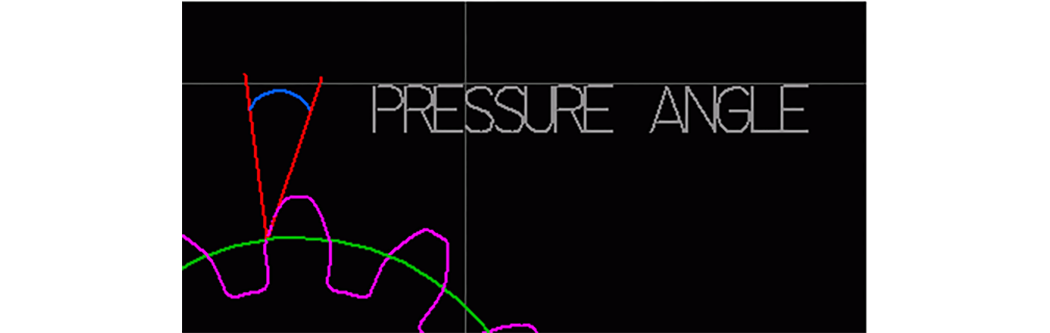
The Pressure Angle is the angle between the gear tooth and a line perpendicular to the pitch circle. (It is the same angle as the angle between the line of action and a line tangent to the pitch circle.)
By default, these are automatically computed. Clear the Automatically Pick check box, and any value can be entered. Note that it is possible to enter values that result in gears that are impossible to make. If you make a gear with many fine teeth, where the root fillet radius is less than 0.0155 inches, then no radius is placed. Instead, the radius of the jet will make the radius in the corner.
When the desired settings are selected for the gear or rack, click Go.
The gear (or rack) is placed on the drawing, and is automatically selected to make it easy to move into position.
When the units are set to any metric measurement (meters, centimeters, millimeters), the gear is created in millimeters, using the metric gear dialog. Metric gears with the same module and pressure angle will always mesh together properly, regardless of the number of teeth. See File/Configure Preferences to set metric units.
1. Right-click on Shapes on the left side of the screen.
2. Choose Gear, Rack or Sprocket from the drop-down menu:
3. The Gear, Rack, and Sprocket Shapes Generator dialog appears. Select Metric External (spur) gear as your Shape Type:
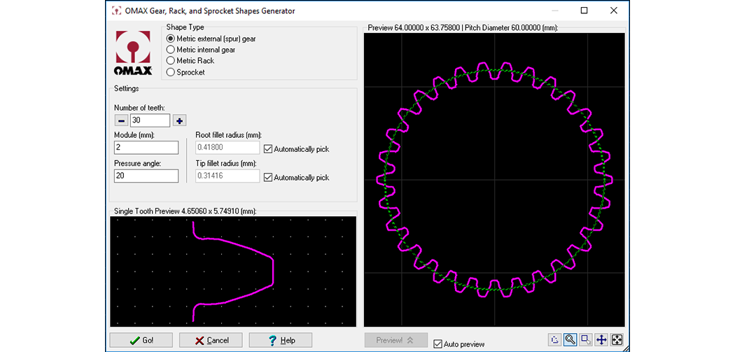
The Gear, Rack, and Sprocket Shapes Generator in Metric units
The large preview window on the right shows the gear that will be generated as a result of the current values. Another window shows a view of a single tooth. Zoom in and out in both of these windows by moving the cursor over the window and using the left mouse button to zoom in and the right mouse button to zoom out.
Enter the number of teeth in the gear. The + and - buttons may also be used to increase and decrease the number of teeth.
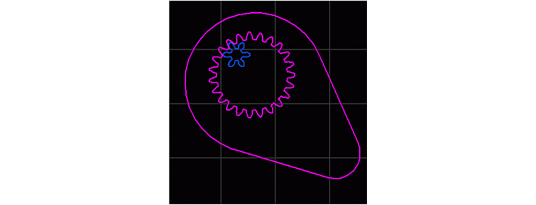
The blue gear is an external gear, the purple gear is an internal gear
The module is the pitch diameter divided by the number of teeth. It is also the length of the "addendum" (the distance from the tip of the tooth to the pitch circle).
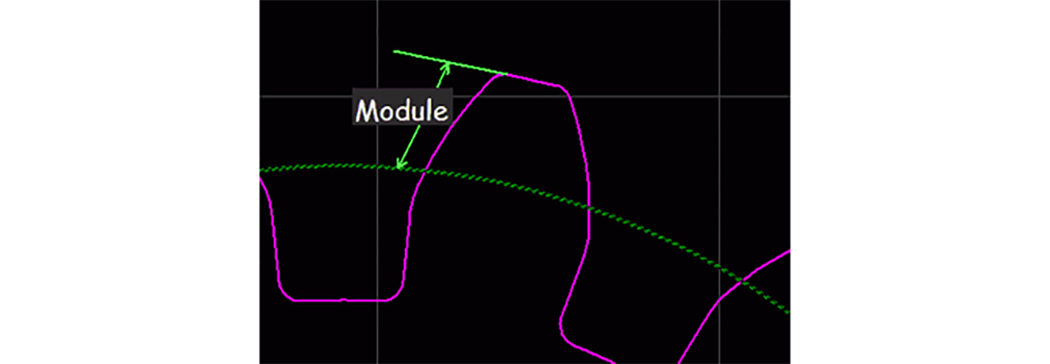
The relationship between the module (M), the number of teeth (N), and the pitch circle diameter (d) is:
d = MN
The Pressure Angle is the angle between the gear tooth and a line perpendicular to the pitch circle. (It is the same angle as the angle between the line of action and a line tangent to the pitch circle.)
By default, these are automatically computed. Clear the Automatically Pick check box, and any value can be entered. Note that it is possible to enter values that result in gears that are impossible to make. If you make a gear with many fine teeth, where the root fillet radius is less than 0.397 mm, then no radius is placed. Instead, the radius of the jet will make the radius in the corner. When the desired settings are selected for the gear or rack, click Go.
The gear (or rack) is placed on the drawing, and is automatically selected to make it easy to move into position.
1. Right-click on the Shapes button on the left side of the screen.
2. Choose Gear, Rack or Sprocket from the drop-down menu:
3. The Gear, Rack, and Sprocket Shapes Generator dialog is displayed. Use this dialog to select Sprocket as your Shape Type:
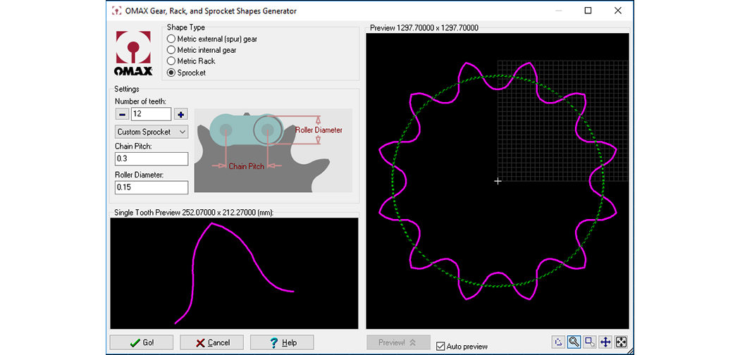
The Gear, Rack, and Sprocket Shapes Generator with Sprocket Selected
The large preview window on the right shows the sprocket that will be generated as a result of the values provided. The lower left window shows a view of a single sprocket tooth. You can zoom in and out in both of these windows by moving the cursor over the window and using the left mouse button to zoom in and the right mouse button to zoom out.
Enter the number of teeth in your sprocket. The + and - buttons may also be clicked to increase and decrease the number of teeth.
Use the drop-down menu where "Custom Sprocket" appears as a default and select a predefined sprocket type from the list provided.
Measure the chain pitch as illustrated below and then enter that value.
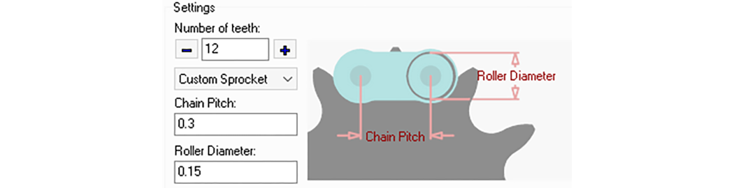
The Chain Pitch and Roller Diameter
Measure the roller diameter as illustrated above then enter that value.
When the desired settings appear in the Sprocket generator, click Go.
Your sprocket design is placed on the drawing and automatically selected to make it easy to move into position.
Gears with fewer than six teeth may not mesh properly. If you need to create a gear with fewer than six teeth, you will probably need to do some manual editing of the generated gears.
Certain combinations of gear attributes will not work with the Gear Generator. In particular, gears with large numbers of teeth and/or large pressure angles may not completely draw, or may draw with extra or overlapping entities. When these problems occur, they are obvious in the preview. In these situations, either choose different attributes for the gear, or edit the gear using standard LAYOUT tools after the geometry has been generated.
The following information explains how LAYOUT creates a gear.
Gears generated with the gear maker are equivalent to those cut with a profile cutter using a milling machine and dividing head. The profile follows an involute curve from the base circle to the outside diameter.
The addendum, dedendum, tooth thickness and root radius are as specified in "Machinery’s Handbook." Between the base circle and the root radius the profile is a straight radial line. A radius of 5% of the tooth thickness is used to fillet the junction of the involute and the outside diameter.
Any two gears of the same pitch and pressure angle made with LAYOUT should roll properly with each other and with their corresponding rack. They are equivalent to catalog gears that you might buy. The tooth strength at the root of such gears is not as great as may be obtained with custom designed gears that run in matched pairs. Such custom design is beyond the scope of LAYOUT.
The involute curve is fitted more closely with LAYOUT than can be done with the normal series of profile cutters used with a milling machine. The involute curve is approximated by fitting a series of arcs to the true curve. By turning on Dots, the individual arcs can be viewed. The points at the start and end of each arc are exact points on the involute.
Fewer arcs are used on each tooth as the number of teeth increases because the involute more nearly approaches a true arc. In fact, as the number of teeth approaches infinity, the tooth shape becomes the straight side of a rack (arc of zero curvature). This approach provides high accuracy without requiring an unwieldy number of arc entities.
The GlobalMAX control software slows the speed of the abrasive jet nozzle in areas of fine detail to avoid errors due to the lag of the jet as it passes through the material. At low speeds, the jet cuts a wider kerf, which requires a greater tool offset. For this reason, fine teeth may be thinner than expected.
Maximum precision can be attained by cutting a few teeth on a trial basis and measuring their width. The tool offset is then increased by an amount equal to half the difference between the expected width and the actual width. The final gear is then cut using this new offset. In effect, this procedure uses the actual gear tooth for a tool offset test.
