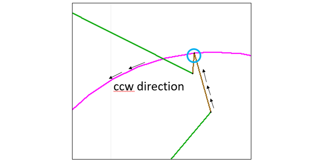
A nozzle path is used by the ProtoMAX when machining a part. The nozzle path must be one continuous path, although the abrasive jet can be turned off for during sections of the path by using the Quality of traverse.
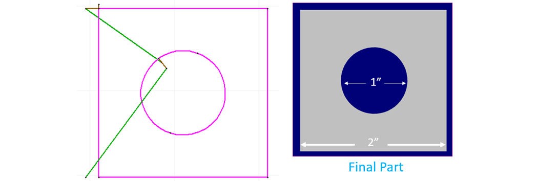
Sample Drawing requiring that a nozzle path be added to cut the part
Lead-ins
Pierce on the inside
The tool offset is programmed to cut to the left side of the lead-in line by default
Question: Looking at the circle below, which side do we want the nozzle to cut on? Inside or outside the circle?
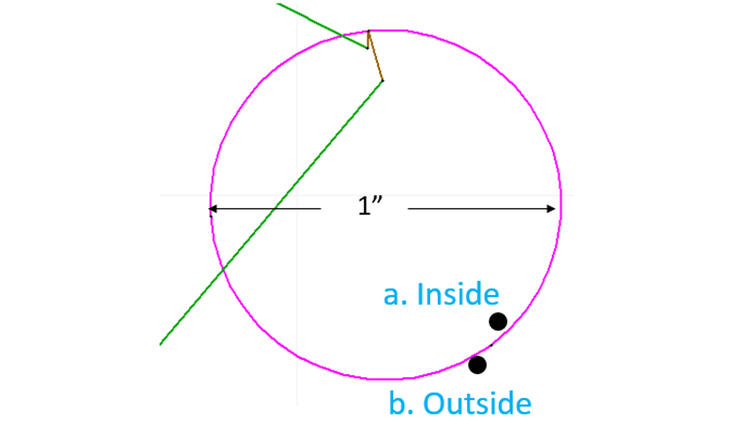
Answer:Cut on the inside to maintain the hole diameter at 1 in.
Question: Which direction should the nozzle travel if we want it to cut inside the circle, knowing it will cut to the left of our line? Clockwise or counterclockwise?
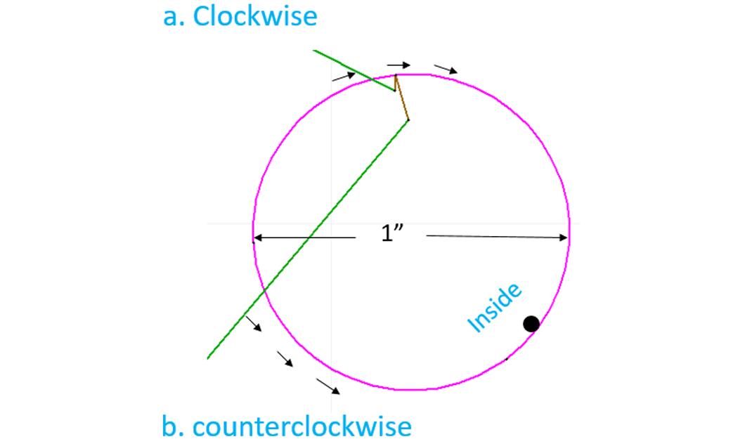
Answer: Travel in the counterclockwise direction so it cuts to the inside of the internal geometry.
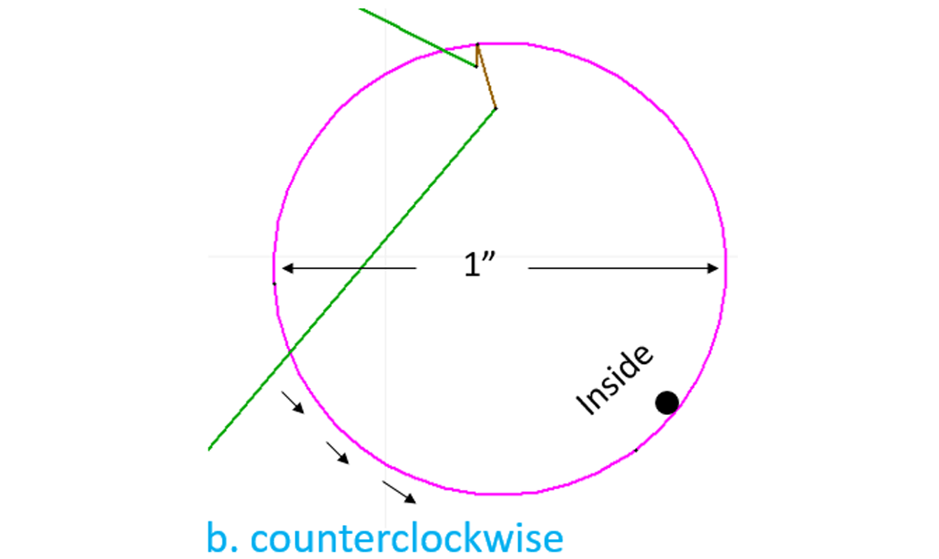
Lead ins (on internal geometry)
Draw lead in longer than lead out
Place pierce point in the material scrap area (inside)
Cut in a counterclockwise direction so it cuts on the inside of the geometry
Draw the lead in so the least sharp turn points in the counterclockwise (ccw) direction on internal geometry
Point the lead in the direction you want the nozzle to travel (ccw)
Question: Which side of the external geometry (the box part below ) do we want the nozzle to cut if we want to maintain our part dimension as drawn? Outside or inside?
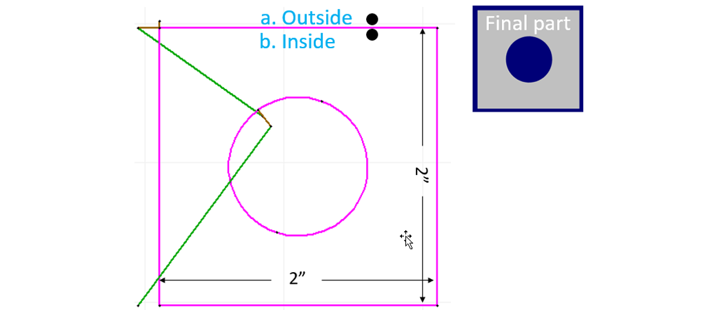
Answer: We want to cut on the outside of the box
Question: Which direction does the nozzle need to travel to cut on the outside of our box? Clockwise or counterclockwise?
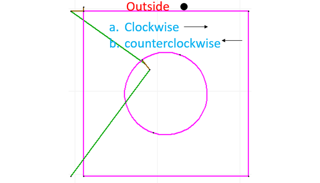
Answer: We want the nozzle to travel in the clockwise direction on external geometry so the kerf is on the left, or outside the geometry:
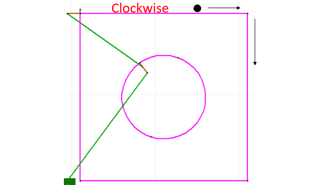
Question: Which direction will the nozzle travel when it reaches the end-point of the lead in for the following example?
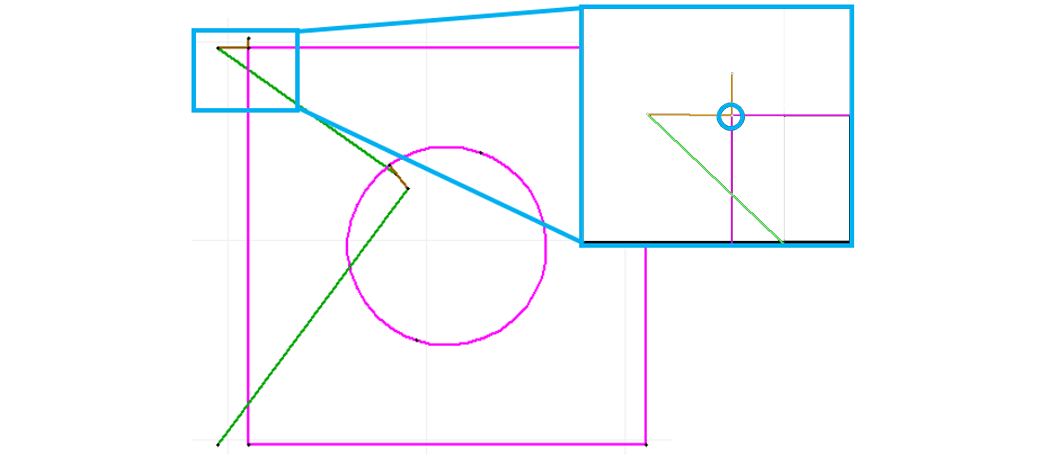
Straight
Up
Down
Answer: The nozzle will continue to go straight when it reaches the end-point of the lead in in this drawing because it is the least sharp angle or turn to follow:
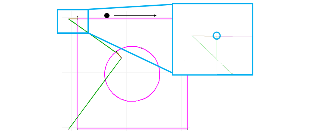
Avoid traveling over something already cut:
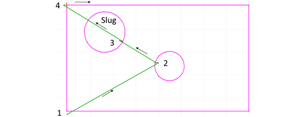
To avoid a potential collision with the slug:
Move the lead in/out to the opposite side of the circle
Change the traverse line to a heads-up traverse
Move the lead in/out on the box to the lower left or top of the box
Route the nozzle path to cut internal geometries first (keeps material stable during the cutting process)
Place your lead i/o on the side of the geometry you want to cut out (place them in the scrap)
Draw your lead in longer and your lead out shorter (helps you know which direction the nozzle is traveling)
Draw your lead i/o and traverse lines to minimize nozzle travel (saves time when cutting)
Draw the nozzle path to avoid traveling over already cut pieces (slugs) that may cause nozzle “collisions”
Specify a narrow angle and use lines for your lead i/o to minimize machine marks where the nozzle finishes cutting
The software will cut to the left of the line, by default
Internal geometries are cut to the left (counterclockwise)
External geometries are cut to the right (clockwise)
The machine path will automatically route the nozzle in the direction of least resistance (the least sharp turn)
How you draw your lead-i/o will affect the direction the nozzle travels (clockwise or counterclockwise) – point the lead in the direction you want the path to go
For best offset performance, avoid small entities in inside corners