
________________________________________
The advanced version of AutoPath gives you complete control over lead geometry and path options.
The settings that you define in this dialog will also be applied when you select AutoPath Quick.
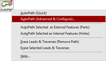
To open the AutoPath dialog, right-click on , and select .

Hover mouse over image to view full size.
Upon running the advanced AutoPath command, a simple cleaning of the drawing takes place that will erase duplicate entities, close gaps, and remove short entities. The command will initially remove existing leads and traverses, but those can be restored by using the "Keep Leads" and "Keep Traverses" commands.
| Element | Description |
|---|---|
Start Point  |
A starting point is where the tool path should begin. A traverse is drawn from this location to the first lead-in of the path. Only one starting point (among nine possible position points) can be set at any given time. |
End Point  |
An ending point is where the tool path should end. A traverse is drawn from the final lead-out to the path to this location. Only one ending point (among nine possible position points) can be set at any given time. If it is desired to have the path end with the final led-out instead of having a final traverse after the lead-out, right-click on any of the ending point buttons. Doing so results in having none of the ending point buttons down, and the path will be redrawn without a final traverse. Note
A path's ending point can be set in a different position from the starting point. |
There are four unique path strategies that can be used to make a tool path. [These buttons are all enabled as a default.]
The button for each strategy works as a toggle and AutoPath will determine the best strategy for the tool path (governed by the shortest distance) among those strategies that are toggled to "ON". If it is desired to only use one particular strategy, then that one strategy should be the only one that is on while the rest are turned off.
If all strategies are turned off, AutoPath will pick the best option from among the different strategies as though they were all turned on.
| Button | Name | Description |
|---|---|---|

|
Zig-Zag Traveling Horizontally |
Results in a path where the zig-zag behavior runs up and down while making a horizontal progression |

|
Zig-Zag Traveling Vertically |
Results in a path where the zig-zag behavior runs left and right while making a vertical progression. |

|
Nearest Neighbor | Uses logic where, after one feature of a path has been processed, the next feature that gets processed will likely be the closest feature to the current one |

|
Traveling Salesperson | Uses logic that involves determining the approximate shortest route among a given set of path features. |
| Element | Description |
|---|---|
| External Offsets... | This specifies on which side of the outermost tool path (or "outside") the offset will be. The default is to offset to the left (or clockwise). |
| Internal Offsets... | This specifies on which side of the innermost tool path (those inside the part) the offset will be. The default is to offset to the left (or counterclockwise), which will usually put the offset on the inside of the tool path. |
The following settings are available for both lead ins and lead outs.
| Element | Description |
|---|---|
| Length | The length of the lead-in/out. All lead-ins will be the same length. All lead-outs will also be the same length. |
| Angle | The Angle between the lead-in/out and an imaginary line drawn perpendicular to the tool path. The angle between the lead-in and the lead-out will be the sum of both angles. |
| Style | Choose a lead-in/lead-out style of either Line or Arc. Choosing Arc-style leads while using the Automatic option with Generate Tool Path will probably lead to errors. |
| Element | Description |
|---|---|
| Keep leads |
This feature allows most leads that exist in the drawing, prior to launching the AutoPath form, to be kept in the drawing. The AutoPath algorithm will take these existing leads into consideration as it generates the tool path. Note:
When keeping existing leads, the AutoPath algorithm will: 1) Check if the lead-ins/outs are valid or not. If they are not valid, such as a lead that is drawn on the wrong side of an inner profile, AutoPath will remove the incorrect leads and create a new one automatically for the profile. 2) In instances where multiple lead-ins/outs were drawn for one profile, AutoPath will keep one set and remove the other lead-in/outs. AutoPath only supports one set of lead-ins/outs for each profile. |
| Keep traverses (attached to leads) |
This feature allows any traverses that are connected to leads to be kept. When AutoPath's algorithm designs the path the existing traverses will not be disturbed. Traverses that are connected to entities other than leads or are not connected to anything will be removed. note:
"Keep existing traverses" will only be enabled if "Keep existing leads" is checked. The best scenario for using "Keep existing leads" and "Keep existing traverses" is when leads and traverses are hand-drawn for certain features in a drawing, but there are other opportunities where the AutoPath can fill in the rest of the path. If a drawing has all of its features already drawn for a tool path prior to using the AutoPath form and "Keep existing leads" and "Keep existing traverses" are checked, then the AutoPath form will be ineffective for generating a tool path. |
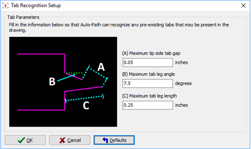
Use the Tab Recognition Setup dialog to define characteristics for AutoPath to recognize pre-drawn tabs in a drawing.

| Element | Description |
|---|---|
| Maximum tip side tab gap | Defines the maximum distance between the tip-side endpoints of the two legs of the tab. Any gap of a lesser size than the maximum will also be considered. |
| Maximum tab leg angle | Defines the maximum amount of degrees a tab leg can be angled relative to the entities that make up the part to be cut. Any lesser degree angle than the maximum will also be considered. |
| Maximum tab leg length | Defines the maximum length that any tab leg can have in order to be recognized. Regardless of whether or not the legs of the tab are the same size, the tab will be recognized so long as the maximum value is set at or higher than the length of both of the legs of the tab. |
There are four strategies to pick from in regards to how traverses will be drawn for the path:
| Element | Description |
|---|---|
| Use direct routes (always heads down, straight traverses) | This option should only be used if the confidence that avoiding potential collisions among the features of a part is high. |
| Use circuitous routes | This option will draw heads-down traverses that will be laid out in such a manner that collisions with features that would already be cut out would be avoided. |
| Use mix of heads up and heads down (recommended) | This option will use a combination of heads-up and heads-down traverses as needed to avoid potential collision spots. |
| Use Heads-Up Traverses always | For this option, every traverse will be drawn as a Heads-Up Traverse in the path. |
| Element | Description |
|---|---|
| Always preview generic drawing |
|
| Always preview actual drawing |
|
| Manually update actual preview |
|
Zoom controls provide added control over being able to zoom in and out in the preview window as well as what is displayed:
| Element | Description |
|---|---|
Show endpoint dots  |
Turning on this feature will cause the preview window to display the endpoints of each entity. Turning off the feature will hide the endpoints. |
Zoom Cursor  |
The Zoom Cursor function will allow the magnifying glass operation for zooming in and out of the preview window. In this mode, holding down the left mouse button will zoom in on the drawing while holding down the right mouse button will cause the drawing to zoom out. |
Zoom Window  |
In this mode, a zooming window can be drawn on the drawing. When the zoom window is drawn, the zoom window will zoom into the area of the drawn window. |
Zoom Extents  |
This button will cause the preview window to zoom to the extents of all of the entities that are in the drawing. |
Information about the path only shows when "Preview actual drawing" is checked. It provides some basic information about the path such as…
| Element | Description |
|---|---|
| Predominant Strategy Used | This provides information on which strategy, among those that are active, was used the most to implement the tool path for the drawing. |
| Total Path Distance | This provides the total sum of lengths of all of the entities that comprise the tool path. |
| Element | Description |
|---|---|
| Go! | Causes a tool path to be generated for the drawing using the settings that are on the form. |
| Cancel |
Cancels the tool path generation process and closes the dialog box. |
| Help | Opens the help screen to this page. |
| Default |
Click to restore all of the settings on this form to their default values. Right-click the button to display a menu: Load Setup Opens a dialog that allows a settings file to be chosen that sets the buttons and values of the AutoPath form to whatever is inside the settings file. Save Setup Opens a dialog that allows a settings file to be saved containing the settings of how the AutoPath form is set. |